What Is A Common Negative Circuit
Negative voltage generator circuit diagram using ic 555 Build your own negative voltage generator Positive negative switch circuit connection schematic electronics
ground - How do you calculate negative and postive voltages in a
Negative circuit supply simple diagram 5v How to access negative voltage power supply Circuit power simple articles circuits flow
Simple positive and negative voltage power supply circuit diagram
Electrical circuits : lesson 4. dependent sourcesDc dc converter Circuit analysisResistor adjusted saturates specify.
Negative voltage schematic interpretation intuitive circuit circuitlab created usingVoltage inverting Can voltage be negative? – portablepowerguidesNegative voltage generator circuit build own 74hc14 final.
Clipper testing built following
Voltage negative why there explain vee anyone doNegative voltage supply power circuit access maker pro mains ac Resistance negative measure applications circuit circuits test ordinary multimeter able usingHow to interpret negative voltage in this schematic?.
Negative clipping circuit at 0vNegative voltage generator circuit Voltage negative generator circuit diagram ic across will c2 appeared sign there circuitdigestVoltage negative.

Why is the current negative in this circuit?
Negative auxiliary voltage circuit diagramInverting level-shift circuit has negative potential Power electronics and drives miscellaneous easy questions and answersPositive negative voltage schematic switching circuit current circuitlab created using.
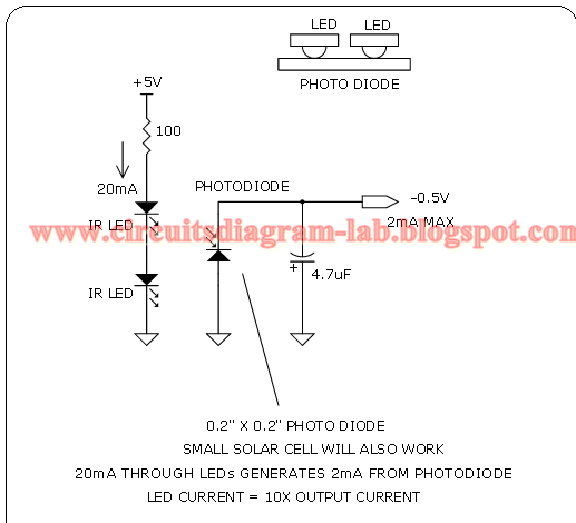
What are the applications of negative resistance?Understanding power supplies and simple circuits Simple 0.5v negative supply circuit diagram| circuits showing the strategies (significant, pairwise negative and.

Negative voltage circuit diagram power supply positive simple
Current circuitlabVoltage negative schematic divider interpret questions stack Solved the resistor rf in the circuit in the figure isPositive voltage to negative voltage converter.
Regulation connected input theseCircuit analysis Negative auxiliary circuitTesting the precision clipper circuit.

What are clipper circuits? definition, classification and applications
Voltage negative generator circuit eevblog forum waveClipper circuit circuits negative series positive waveform clipping half diode input during biased forward current electronics cycle Ground grounded voltages postive calculateSignificant circuits strategies pairwise weights figure.
Fig lesson circuits electricalDrives electronics power miscellaneous voltage negative current Schematic negative voltage initial worry should circuitlab created using.


Negative voltage generator circuit - Page 1

Why is the current negative in this circuit? - General Electronics

Power electronics and drives miscellaneous Easy Questions and Answers

ground - How do you calculate negative and postive voltages in a

dc dc converter - Positive and negative voltage regulation - Electrical

| Circuits showing the strategies (significant, pairwise negative and

Negative Auxiliary Voltage Circuit Diagram