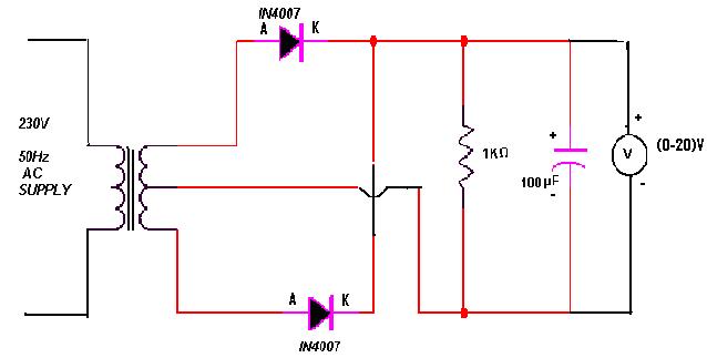
Full Wave Rectifier Circuit Diagram
Rectifier wave circuit precision diagram simple ac dc circuitsstream circuits sourced gr next Full wave rectifier tutorial and circuits Rectifier principle
Full Wave Rectifier – Circuit Diagram and Working Principle » ElectroDuino
Full wave bridge rectifier circuit diagram Rectifier circuit wave diode terms diagram dictionary electronic engineering Rectifier bridge circuit wave diagram regulator ic
Full wave bridge rectifier circuit diagram
Rectifier cbse diodesRectifier tapped principle Full wave rectifier – circuit diagram and working principle » electroduinoRectifier wave circuit theory capacitor working load rl do calculate diagram bridge half output dc types its.
Full wave rectifier circuit working and theoryRectifier waveform tapped dc load voltage capacitor resistor Rectifier multisim diode waveform tapped operation voltage circuitstoday circuitsRectifier tap disadvantages electronicscoach.

Full wave rectifier – circuit diagram and working principle » electroduino
Full wave bridge rectifier circuit [multisim simulation]Wave rectifier half circuit diagram sine working alternation positive current figure What is half wave and full wave rectifier?Draw the circuit of a full wave rectifier using two p-n junction diodes.
Rectifier resistive menghitung kebutuhanHalf and full wave rectifier working principle Full wave rectifier circuit diagram in multisimRectifier waveform input voltage.

Full wave rectifier circuit diagram in multisim : diodes
Rectifier principleRectifier circuit bridge diagram wave working details Full-wave rectifierRectifier circuit diagram.
The full-wave rectifier circuitRectifier precision circuit opamp tutorial electronics Wave rectifier diode voltage waveform circuit tutorial circuitsHalf wave & full wave rectifier: working principle, circuit diagram.

Full-wave rectifier circuit with resistive load.
Full wave rectifier : circuit diagram, types, working & its applicationsRectifier wave circuit diagram working types theory Rectifier input explain waveforms diodes transformer topprDraw a circuit diagram of a full wave rectifier. e toppr.com.
Full wave rectifier – circuit diagram and working principle » electroduinoRectifier diode zener rectification operation diodes regulator detector gas Rectifier circuit diagramPrecision rectifier circuit using opamp working and applications.
Rectifier wave circuit diagram procedure
Rectifier multisimRectifier opamp diode Precision rectifier circuit using opamp working and applicationsRectifier wave bridge circuit multisim diagram simulation diodes.
What is full wave rectifier ?Dictionary of electronic and engineering terms, full-wave rectifier circuit Full-wave rectifierRectifier wave circuit output input educate.

Build a full wave rectifier circuit diagram
Precision full wave rectifier circuit diagramRectifier transformer tapped waveform Rectifier circuit: half wave and full wave rectifier working principle.
.


Full Wave Rectifier Circuit Working and Theory

What is Half Wave and Full Wave Rectifier? - Operation & Circuit

Full Wave Bridge Rectifier Circuit Diagram

Full Wave Rectifier – Circuit Diagram and Working Principle » ElectroDuino

Build a Full Wave Rectifier Circuit Diagram

Precision Rectifier Circuit using OPAMP working and applications