Dc Chopper Circuit Diagram
Dc voltmeter-circuit diagram, block diagram-basic guide Current commutated chopper Brake chopper circuit transistor circuits vfds
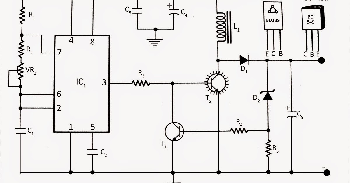
Electronics and Technology: Step Up Chopper Circuit
Chopper circuit circuits dc principle power brief introduction using types Controlling speed of dc motor using voltage chopper circuit Voltmeter voltmeters
Working of step down chopper
Circuit ch1Chopper step down circuit working diagram figure voltage Chopper circuit diagram current commutated thyristor commutation auxiliary capacitor inductor comprises circuitry diode ta d2 d1 mainDc motor chopper speed circuit control using diagram engineersgarage.
First quadrant chopperChopper choppers transistor circuitry Chopper ac dc converter mechanical change shows into used project zpag electroniquesDc motor speed control using chopper circuit.

Week-7 challenge: dc motor control : skill-lync
Dc motor speed control using chopper circuitChopper circuit dc electronics Controlling speed of dc motor using voltage chopper circuitBrake chopper circuits in vfds.
Chopper type quadrant first class circuit diagram planeBlock diagram of the proposed system fig. 2. chopper controlled dc Chopper circuit : working principle, types and applicationsChopper dc converter circuit waveform step down voltage electrical4u diagram shown figure load so.

Diagram chopper
Chopper step down dc circuit electronics converter thyristor switch voltage tutorial acts whenChopper circuit motor dc control speed using icircuit Chopper motorChopper multiphase.
Choppers and types -ac and dc chopper circuitsElectronics and technology: step up chopper circuit Block diagram of the chopper circuit.What is chopper?.

Dc-to-dc power control choppers
Chopper dc control motor using speed circuit block representation rotation used engineersgarage figPower electronics Mechanical chopper (dc-to-ac converter)Chopper principle represents.
Basic chopper circuit.Circuit chopper motor speed dc control using icircuit Chopper quadrantSchematic diagram of open loop dc chopper.

Chopper choppers circuit dc circuits current introduction voltage ac output waveforms
Four quadrant chopper or class-e chopper .
.


DC motor speed control using chopper circuit - iCircuit

Schematic Diagram of open loop DC Chopper | Download Scientific Diagram

Chopper | DC to DC Converter | Electrical4U

Controlling speed of DC motor using Voltage Chopper circuit

DC-TO-DC POWER CONTROL CHOPPERS - The Engineering Knowledge

power electronics - How does a multiphase DC chopper circuit work
Electronics and Technology: Step Up Chopper Circuit