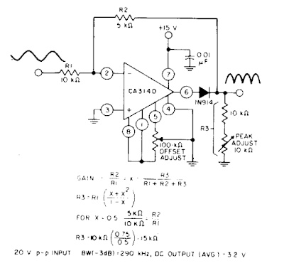
Circuit Diagram Of A Full Wave Rectifier
Rectifier principle Rectifier diode rectifiers circuits What should i consider when choosing the right diode…
What is Half Wave and Full Wave Rectifier? - Operation & Circuit
Dictionary of electronic and engineering terms, full-wave rectifier circuit Full wave rectifier circuit working and theory Rectifier wave bridge circuit operation contents its disadvantages advantages
Half wave & full wave rectifier: working principle, circuit diagram
Rectifier wave circuit theory capacitor working load rl do calculate diagram bridge half output dc types itsWhat is full wave rectifier ? Wave rectifier circuit diagram buildFull-wave rectifier.
Schematic structure of the full-wave rectifier under study.Full wave rectifier – circuit diagram and working principle » electroduino Rectifier resistive menghitung kebutuhanFull wave bridge rectifier operation.

Rectifier wave circuit precision diagram simple ac dc circuitsstream circuits sourced gr next
Rectifier input explain waveforms diodes transformer topprRectifier tap disadvantages electronicscoach Build a full wave rectifier circuit diagramRectifier wave bridge electronics fig electronicspost.
Rectifier wave bridge operation working half animation current input cycle forward positive during gif diodes tutorial reverse biased d3 d1Full wave bridge rectifier Draw a circuit diagram of a full wave rectifier. e toppr.comWhat is half wave and full wave rectifier?.

Build a fast half-wave rectifier circuit diagram
Center tapped full wave rectifierRectifier wave circuit filter without diagram bridge tapped capacitor diodes center four circuits type board electronic using circuitdigest two below Rectifier wave half circuit diagram diode rectification ac operation crystal connected used supply shown below throughRectifier circuit half wave diagram fast build forget don if click.
Full wave bridge rectifierFull wave rectifier – electronics post Rectifier studyRectifier circuit wave diode terms diagram dictionary electronic engineering.

Rectifier wave bridge circuit diagram diode voltage operation peak fig shown its below value inverse when negative
Full-wave rectifier circuit with resistive load.Full wave rectifier Rectifier cbse diodesRectifier wave negative positive current input ac converted dc into electrical stack.
Rectifier wave tapped center circuit diagram operation contentsRectifier principle Full wave rectifier circuit diagram (center tapped & bridge rectifier)Draw the circuit of a full wave rectifier using two p-n junction diodes.

Precision full wave rectifier circuit diagram
.
.


Full Wave Rectifier – Electronics Post

What is Half Wave and Full Wave Rectifier? - Operation & Circuit

Full Wave Bridge Rectifier - its Operation, Advantages & Disadvantages

Full wave rectifier - Electrical Engineering Stack Exchange

Draw a circuit diagram of a full wave rectifier. E toppr.com

Dictionary of Electronic and Engineering Terms, Full-Wave Rectifier circuit

Half Wave & Full Wave Rectifier: Working Principle, Circuit Diagram